F5 BIG-IP multi-cluster ingress for Red Hat OpenShift
Here in this blog, we are going to learn about F5 BIG-IP multi-cluster ingress for Red Hat OpenShift.
Maintaining high availability (HA) and orchestrating smooth application deployments across heterogeneous environments are frequent problems for businesses. Organizations may more successfully handle these problems and give multicluster environments the following functionality by utilizing per-application multi-cluster ingress with F5 BIG-IP and Red Hat OpenShift:
- Adaptable application placement: Enables the distribution of apps among several clusters using a single multicluster ingress.
- Deployment techniques for individual applications: Facilitates A/B and blue-green testing procedures for individual applications.
- Enhance the application’s functionality and performance: Adapt performance and capacity to each application.
- Reconstruction after a disaster: uses settings for single-active applications to support disaster recovery (DR).
- Scalability and availability of clusters: Split up large, independent clusters into several smaller ones to improve infrastructure uptime and manageability.
- Adaptable OpenShift transitions: Allows for partial upgrades and migrations, preventing “all or nothing” situations.
- Layer 4 load distribution: allows for multi-cluster load balancing for traffic that is not HTTP L4.
How is BIG-IP operated?
A Container Ingress Services (CIS) controller is used by F5 BIG-IP to facilitate communication between BIG-IP and OpenShift. Kubernetes manifests, text-based YAML files that specify the resources and parameters required to run apps in a Kubernetes environment, are used to manage BIG-IP configuration.
BIG-IP allows for both a one-tiered and a two-tiered setup for the data plane. BIG-IP routes traffic straight to the workload pod IP in a one-tier configuration. In a two-tier design, it is routed to an API manager, service mesh, ingress controller, or a mix of these.Pod IPs can also be used in this configuration to connect to the second layer, such as the OpenShift router. NodePort and hostNetwork can also be utilized.
Because of its application awareness, BIG-IP is an external load balancer (LB) that may function as a Layer 7 (L7) ingress. Ingress, Routes, and F5 VirtualServer Custom Resources (CR) make this possible. This enables BIG-IP to balance load according to each route’s availability while keeping an eye on the health of OpenShift applications across several clusters.
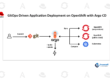
The diagram shows a single-tier multi-cluster setup where traffic is BIG-IP-routed straight to the workload pods:
Note that neither the OpenShift version nor the applications installed in each cluster are need to be the same. Deployment possibilities are substantially enhanced by this flexibility.
A two-tier configuration for several clusters is depicted in this figure:

A two-tier configuration is used to direct traffic to the first tier, or external load balancer, in this case BIG-IP. From there, traffic is sent to another load balancer within the OpenShift cluster. This could be an API manager, a service mesh, another ingress controller, the default OpenShift router (often HAProxy), or any combination of these.
Generally, second-tier load balancers oversee L7 operations, while first-tier load balancers are constrained to Layer 4 (L4) and do not have L7 awareness. However, BIG-IP is fully L7-aware when utilized as an external load balancer. Additional use cases are made possible by this, like grouping several ingresses behind a single virtual IP (VIP) that has the same hostname. Based on the HTTP route, BIG-IP may route traffic to the right second-tier load balancer.
This figure depicts how this two-tier completely L7-aware setup works:

In a two-tier system, the routes of the second tier remain the same. BIG-IP uses its own manifest to raise L7 knowledge to the first tier. These define the traffic routing to the ingress controllers and provide health checks for the OpenShift application pods. It is significant to remember that in a one-tier configuration, only the BIG-IP’s route manifests are required.
How several clusters receive traffic
The Active-Active, Ratio, and Active-Standby multi-cluster load balancing techniques are the three available.
Standard BIG-IP load balancing techniques like round-robin, least-connections, and fastest member are applied when a pool has been chosen.
Intense-Intense
Pods from every cluster are gathered into a single pool, and the load balancer technique assigned to the pool is applied regardless of the target pod’s cluster.
For a given application, traffic can be routed to a certain cluster using A/B and Blue-Green techniques, improving traffic control during upgrades and other testing.
Ratio
The amount of traffic that should be sent to each OpenShift cluster is determined by a ratio that is applied to all services at once. This is a two-tier system in which the cluster is chosen based on a defined ratio, and standard load balancing is then implemented within the cluster’s pool.
Inactive-Standby
Not included are pods from a cluster in which the CIS is in standby, which is advantageous for applications that can run in just one cluster simultaneously.
How it is applied
For DevOps teams, using this multi-cluster solution is rather simple. OpenShift route resources that already exist can be used without being altered. All clusters will automatically use service discovery; only the clusters need to be defined in a CIS ConfigMap. DevOps can manage Layer 4 traffic for multi-cluster in-memory databases or leverage F5 Custom Resources, which offer further HTTP features, in addition to the route resource type.
The multi-cluster manifest arrangement is depicted in this figure:

Additional capabilities offered by F5 BIG-IP include IP Address Management (IPAM), IP intelligence, visibility of SSL/TLS traffic for third-party solution inspection, Advanced WAF, credentials, bot protections, identity aware ingress (SSO, federation, MFA), and more. These can be used directly with the same Extended ConfigMap and F5 CRs, or they can be used using Routes.
Signs and Elevated Availability
All clusters where we wish the apps to be accessible have manifests for the Service resources deployed. Workloads from all other clusters will be taken and will not be considered if a Service manifest is inadvertently erased or if the Kubernetes API cannot be used to access its cluster.
Only in the clusters where CIS instances are installed will the manifests for the HTTP routes or L4 services be established. These manifests therefore have a redundancy of two clusters.
For redundancy, each BIG-IP has two instances of CIS: Primary and Secondary. By default, pushing configuration changes and events to the BIG-IP will fall under the purview of the Primary. If the Primary’s readiness endpoint is unable to provide successful responses, the Secondary will assume responsibility for this task. Be aware that if you use more than two clusters, a CIS instance won’t be operating in any of the extra clusters. No matter how many clusters there are, there will be a total of 4 CIS instances.
This figure stands for the source of truth and HA in the manifest:

Every BIG-IP will have a unique pair of Primary and Secondary CIS, as was previously mentioned. If the neighbor BIG-IP has at least one CIS instance running, this BIG-IP can promote itself to Standby in the event that the Active BIG-IP’s Primary and Secondary CIS fail. We have now closed the loop for every scenario needed to get high availability.
Conclusion
Businesses will require more clusters and flexible application placement as more programs are modernized and refactored under OpenShift. Companies want simplicity, so it’s critical that it’s clear which cluster an application is hosted on.
Because it supports several cluster use cases and enables OpenShift migrations with minimal to no application downtime, the CIS multi-cluster capability is unmatched in the market and does away with the requirement for in-place upgrades.