Gateway Queue Manager Architectural Diagram
Here in this blog, we will learn about Gateway Queue Manager Architectural Diagram.
In today’s interconnected world, organizations face the challenge of integrating numerous applications and systems that operate across various platforms and technologies. The MQ Gateway Queue Manager helps address this challenge by providing a centralized point of control for message routing and transformation. It enables different applications to communicate with each other, regardless of their underlying technology or location.
In the load distribution function of a gateway queue manager, the work is distributed equally by spreading the traffic among several Queue Managers.
In general, queue managers manage the queues that are specific to each application and offer queuing services to those applications. However, by employing the Round-Robin method and the gateway queue manager, it is able to serve the load appropriately.
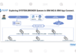
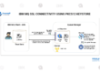
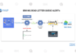
The Client sends messages to an Alias Queue, which is connected to the Gateway Queue Manager. Gateway QM checks the cluster queue definitions because it does not manage the queue. In order to place the messages according to the load, Gateway Queue Manager first determines whether the queues are part of the cluster of QM1, QM2, QM3, and QM4. As a result, the load is distributed fairly.
A queue manager needs a cluster-sender channel and a cluster-receiver channel in order to participate in a cluster.
There are many benefits to using the gateway queue manager, such as message routing and forwarding, load balancing, message transformation, scalability, and high availability.
Gateway Queue Manager Clusters are specialized parts for controlling message flow between systems, while cluster methodology is used for general high availability and load balancing.
An interface queue is created by the application that connects to the Gateway queue manager. The queue is checked for its cluster queue definitions because Gateway Queue Manager does not manage it. The Gateway Queue Manager places the message in the interface queue of one of the four queue managers because it recognizes that QM1, QM2, QM3, and QM4 are in charge of managing the line. It switches between QM1, QM2, QM3, and QM4 when relaying messages to evenly distribute the workload among the Partial Queue Managers.